Как установить конкретную точку зрения, используя перспективный вид с матрицами
В настоящее время я изучаю теорию 3D-рендеринга с книгой «Обучение современному программированию в 3D-графике» и сейчас застрял в одном из упражнений «Дальнейшее изучение» в обзоре четвертой главы, в частности, в последнем упражнении.
Третий вид деятельности был дан ответ в этот вопрос, Я понял это без проблем. Однако, это последнее задание просит меня сделать все это на этот раз, используя только матрицы.
У меня есть частично работающее решение, но оно кажется мне взломанным и, вероятно, не правильным способом сделать это.
Мое решение третьего вопроса заключалось в колебании трехмерного вектора. EКомпоненты x, y и z по произвольному диапазону создали куб с масштабированием с увеличением (слева направо, в исходной точке OpenGL). Я хотел сделать это снова, используя матрицы, это выглядело так:
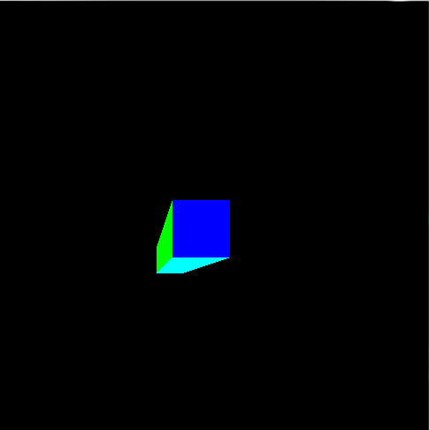
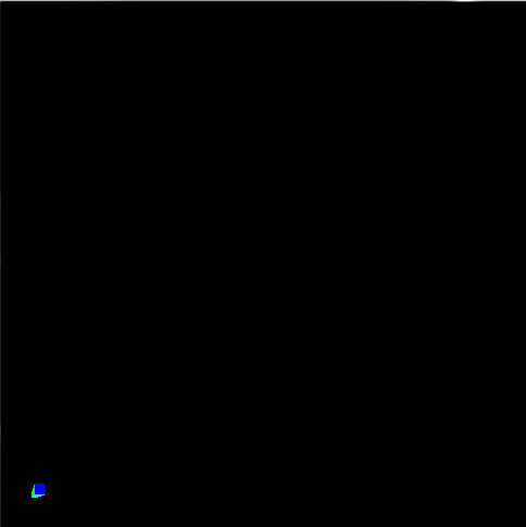
Однако я получаю этот результат с матрицами (игнорируя изменение цвета фона):
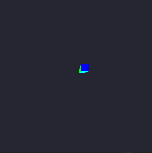
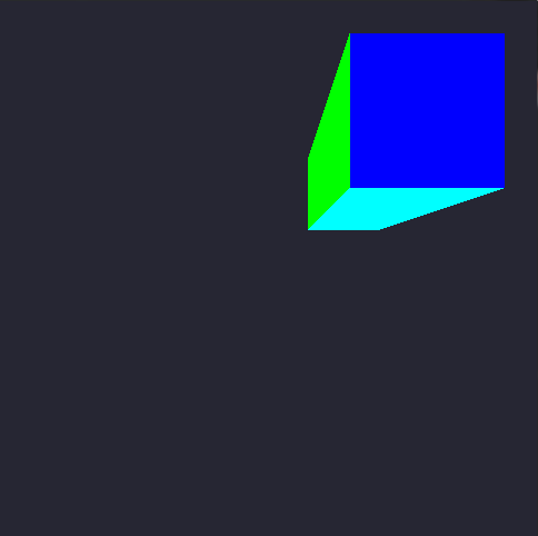
Теперь к коду …
Матрица с плавающей точкой [16] называется theMatrix это представляет матрицу 4×4 с данными, записанными в мажорном столбце со всем, кроме следующих элементов, инициализированных в ноль:
float fFrustumScale = 1.0f; float fzNear = 1.0f; float fzFar = 3.0f;

theMatrix[0] = fFrustumScale;
theMatrix[5] = fFrustumScale;
theMatrix[10] = (fzFar + fzNear) / (fzNear - fzFar);
theMatrix[14] = (2 * fzFar * fzNear) / (fzNear - fzFar);
theMatrix[11] = -1.0f;
тогда остальная часть кода остается такой же, как matrixPerspective учебный урок, пока мы не дойдем до void display()функция:
//Hacked-up variables pretending to be a single vector (E)
float x = 0.0f, y = 0.0f, z = -1.0f;

//variables used for the oscilating zoom-in-out
int counter = 0;
float increment = -0.005f;
int steps = 250;

void display()
{
glClearColor(0.15f, 0.15f, 0.2f, 0.0f);
glClear(GL_COLOR_BUFFER_BIT);

glUseProgram(theProgram);

//Oscillating values
while (counter <= steps)
{
x += increment;
y += increment;
z += increment;

counter++;

if (counter >= steps)
{
counter = 0;
increment *= -1.0f;
}
break;
}

//Introduce the new data to the array before sending as a 4x4 matrix to the shader
theMatrix[0] = -x * -z;
theMatrix[5] = -y * -z;

//Update the matrix with the new values after processing with E
glUniformMatrix4fv(perspectiveMatrixUniform, 1, GL_FALSE, theMatrix);

/*
cube rendering code ommited for simplification
*/

glutSwapBuffers();
glutPostRedisplay();
}
А вот код вершинного шейдера, который использует матрицу:
#version 330

layout(location = 0) in vec4 position;
layout(location = 1) in vec4 color;

smooth out vec4 theColor;

uniform vec2 offset;
uniform mat4 perspectiveMatrix;

void main()
{
vec4 cameraPos = position + vec4(offset.x, offset.y, 0.0, 0.0);

gl_Position = perspectiveMatrix * cameraPos;
theColor = color;
}
Что я делаю не так или что я путаю? Спасибо за время, прочитав все это.
Решение
В OpenGL есть три основных матрицы, о которых вам нужно знать:
-
Модель Matrix D: Отображает вершины из локальной системы координат объекта в мировую систему координат.
-
Посмотреть матрицу V: Отображает вершины из мировой системы координат в систему координат камеры.
-
Проекционная матрица P: Карты (или более подходящие проектов) вершины из пространства камеры на экран.
-
Mutliplied модель и матрица представления дают нам так называемые Модель-вид Матрица М, который отображает вершины из локальных координат объекта в систему координат камеры.

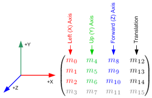
Изменение определенных элементов матрицы вида модели приводит к определенным афинным преобразованиям камеры.
Например, 3 матричных элемента самого правого столбца
 для преобразование перевода. Диагональные элементы
  для масштабное преобразование. Изменение соответствующим образом элементов субматрицы
для преобразования вращения вдоль оси камеры Икс, Y а также Z.
Вышеуказанные преобразования в коде C ++ довольно просты и показаны ниже:
  void translate(GLfloat const dx, GLfloat const dy, GLfloat dz, GLfloat *M)
{
M[12] = dx; M[13] = dy; M[14] = dz;
}

void scale(GLfloat const sx, GLfloat sy, GLfloat sz, GLfloat *M)
{
M[0] = sx; M[5] = sy; M[10] = sz;
}

void rotateX(GLfloat const radians, GLfloat *M)
{
M[5] = std::cosf(radians); M[6]  = -std::sinf(radians);
M[9] = -M[6];              M[10] = M[5];
}

void rotateY(GLfloat const radians, GLfloat *M)
{
M[0] = std::cosf(radians); M[2]  = std::sinf(radians);
M[8] = -M[2];              M[10] = M[0];
}

void rotateZ(GLfloat const radians, GLfloat *M)
{
M[0] = std::cosf(radians); M[1] = std::sinf(radians);
M[4] = -M[1];              M[5] = M[0];
}
Теперь вы должны определить матрицу проекции п.
- Ортографическая проекция:
// These paramaters are lens properties.
// The "near" and "far" create the Depth of Field.
// The "left", "right", "bottom" and "top" represent the rectangle formed
// by the near area, this rectangle will also be the size of the visible area.
GLfloat near   = 0.001, far   = 100.0;
GLfloat left   = 0.0,   right = 320.0;
GLfloat bottom = 480.0, top   = 0.0;

// First Column
P[0] = 2.0 / (right - left);
P[1] = 0.0;
P[2] = 0.0;
P[3] = 0.0;

// Second Column
P[4] = 0.0;
P[5] = 2.0 / (top - bottom);
P[6] = 0.0;
P[7] = 0.0;

// Third Column
P[8] = 0.0;
P[9] = 0.0;
P[10] = -2.0 / (far - near);
P[11] = 0.0;

// Fourth Column
P[12] = -(right + left) / (right - left);
P[13] = -(top + bottom) / (top - bottom);
P[14] = -(far + near) / (far - near);
P[15] = 1;
- Перспективная проекция:
// These paramaters are about lens properties.
// The "near" and "far" create the Depth of Field.
// The "angleOfView", as the name suggests, is the angle of view.
// The "aspectRatio" is the cool thing about this matrix. OpenGL doesn't
// has any information about the screen you are rendering for. So the
// results could seem stretched. But this variable puts the thing into the
// right path. The aspect ratio is your device screen (or desired area) width
// divided by its height. This will give you a number < 1.0 the the area
// has more vertical space and a number > 1.0 is the area has more horizontal
// space. Aspect Ratio of 1.0 represents a square area.
GLfloat near        = 0.001;
GLfloat far         = 100.0;
GLfloat angleOfView = 0.25 * 3.1415;
GLfloat aspectRatio = 0.75;

// Some calculus before the formula.
GLfloat size   =  near * std::tanf(0.5 * angleOfView);
GLfloat left   = -size
GLfloat right  =  size;
GLfloat bottom = -size / aspectRatio;
GLfloat top    =  size / aspectRatio;

// First Column
P[0] = 2.0 * near / (right - left);
P[1] = 0.0;
P[2] = 0.0;
P[3] = 0.0;

// Second Column
P[4] = 0.0;
P[5] = 2.0 * near / (top - bottom);
P[6] = 0.0;
P[7] = 0.0;

// Third Column
P[8]  = (right + left) / (right - left);
P[9]  = (top + bottom) / (top - bottom);
P[10] = -(far + near) / (far - near);
P[11] = -1.0;

// Fourth Column
P[12] = 0.0;
P[13] = 0.0;
P[14] = -(2.0 * far * near) / (far - near);
P[15] = 0.0;
Тогда ваш шейдер станет:
#version 330

layout(location = 0) in vec4 position;
layout(location = 1) in vec4 color;

smooth out vec4 theColor;

uniform mat4 modelViewMatrix;
uniform mat4 projectionMatrix;

void main()
{
gl_Position = projectionMatrix * modelViewMatrix * position;
theColor    = color;
}
Список используемой литературы:
http://blog.db-in.com/cameras-on-opengl-es-2-x/
http://www.songho.ca/opengl/gl_transform.html
Другие решения
