Нарисуйте дугу и переопределите boundingRect (), shape ()
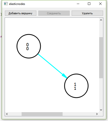
у меня есть class Edge : public QGraphicsItem, который реализует рисование стрелок от одного узла к другому (экран ниже).
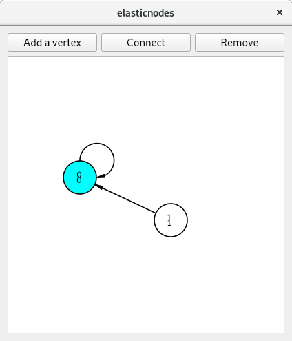
Теперь мне нужно добавить возможность рисовать на себе стрелку (дуги).
Я не могу нарисовать дугу, переопределить boundingRect() а также shape(),
Код ниже, где я рисую стрелку или дугу. Полный проект здесь -> GitHub.
Edge::Edge(Node *sourceNode, Node *destNode)
: id(_idStatic++), arrowSize(15)
{
setFlag(QGraphicsItem::ItemIsSelectable);
source = sourceNode;
dest = destNode;
source->addEdge(this);
if(source != dest)
dest->addEdge(this);
adjust();
}

QPolygonF Edge::nPolygonMath() const {
QPolygonF nPolygon;
if (source != dest) {
QLineF line = QLineF(sourcePoint.x(), sourcePoint.y(), destPoint.x(), destPoint.y());
qreal radAngle = line.angle() * M_PI / 180;
qreal selectionOffset = 3;
qreal dx = selectionOffset * sin(radAngle);
qreal dy = selectionOffset * cos(radAngle);
QPointF offset1 = QPointF(dx, dy);
QPointF offset2 = QPointF(-dx, -dy);
nPolygon << line.p1() + offset1
<< line.p1() + offset2
<< line.p2() + offset2
<< line.p2() + offset1;
} else {
nPolygon << mapFromItem(source, -Node::Radius, -Node::Radius)
<< mapFromItem(source, Node::Radius, -Node::Radius)
<< mapFromItem(source, Node::Radius, Node::Radius)
<< mapFromItem(source, -Node::Radius, Node::Radius);
}
return nPolygon;
}

QRectF Edge::boundingRect() const
{
if (!source || !dest)
return QRectF();

return nPolygonMath().boundingRect();

}

QPainterPath Edge::shape() const{
QPainterPath ret;
ret.addPolygon(nPolygonMath());
return ret;
}

void Edge::paint(QPainter *painter, const QStyleOptionGraphicsItem *option, QWidget *)
{
if (!source || !dest)
return;

painter->setPen(QPen((option->state & QStyle::State_Selected ? Qt::cyan: Qt::black), 2, Qt::SolidLine, Qt::RoundCap, Qt::RoundJoin));
if (source != dest) {
QLineF line(sourcePoint, destPoint);
if (qFuzzyCompare(line.length(), qreal(0.)))
return;

// Draw the line itself
painter->drawLine(line);

// Draw the arrows
double angle = std::atan2(-line.dy(), line.dx());

QPointF destArrowP1 = destPoint + QPointF(sin(angle - M_PI / 1.8) * qMin(arrowSize, line.length()),
cos(angle - M_PI / 1.8) * qMin(arrowSize, line.length()));
QPointF destArrowP2 = destPoint + QPointF(sin(angle - M_PI + M_PI / 1.8) * qMin(arrowSize, line.length()),
cos(angle - M_PI + M_PI / 1.8) * qMin(arrowSize, line.length()));

painter->setBrush((option->state & QStyle::State_Selected ? Qt::cyan: Qt::black));
painter->drawPolygon(QPolygonF() << line.p2() << destArrowP1 << destArrowP2);
} else {
painter->drawArc(mapFromItem(source, Node::Radius, 0).x(),
mapFromItem(source, Node::Radius, 0).y(),
2 * Node::Radius, 2 * Node::Radius, 16 * -90, 16 * 180);

}
}
Решение
Прямоугольник, который нужен как boundingRect() должен иметь как нижний левый центр круга, я также удалил nPolygonMath и вместо этого я использовал форму, чтобы вернуть QPainterPathи это используется в boundingRect():
edge.h
#ifndef EDGE_H
#define EDGE_H

#include <QGraphicsItem>

class Node;

class Edge : public QGraphicsItem
{
public:
Edge(Node *sourceNode, Node *destNode);
virtual ~Edge();
const uint id;
Node *sourceNode() const;
Node *destNode() const;

void adjust();

enum { Type = UserType + 2 };
int type() const override { return Type; }

protected:
QRectF boundingRect() const override;
QPainterPath shape() const override;
void paint(QPainter *painter, const QStyleOptionGraphicsItem *option, QWidget *widget) override;
private:
Node *source, *dest;
QPointF sourcePoint;
QPointF destPoint;
qreal arrowSize;
static uint _idStatic;
};

#endif // EDGE_H
edge.cpp
#include "edge.h"#include "node.h"
#include <qmath.h>
#include <QPainter>
#include <QStyleOption>uint Edge::_idStatic = 0;

Edge::Edge(Node *sourceNode, Node *destNode)
: id(_idStatic++), arrowSize(15)
{
setFlag(QGraphicsItem::ItemIsSelectable);
source = sourceNode;
dest = destNode;
source->addEdge(this);
if(source != dest)
dest->addEdge(this);
adjust();
}

Edge::~Edge()
{
source->removeEdge(this);
if (source != dest)
dest->removeEdge(this);
}

Node *Edge::sourceNode() const
{
return source;
}

Node *Edge::destNode() const
{
return dest;
}

void Edge::adjust()
{
if (!source || !dest)
return;

if(source != dest) {
QLineF line(mapFromItem(source, 0, 0), mapFromItem(dest, 0, 0));
qreal length = line.length();

prepareGeometryChange();
if (length > qreal(2 * Node::Radius)) {
QPointF edgeOffset((line.dx() * Node::Radius) / length, (line.dy() * Node::Radius) / length);
sourcePoint = line.p1() + edgeOffset;
destPoint = line.p2() - edgeOffset;
} else {
sourcePoint = destPoint = line.p1();
}
} else {
sourcePoint = mapFromItem(source, 0, Node::Radius);
destPoint = mapFromItem(source, Node::Radius, 0);
prepareGeometryChange();
}
}

QPainterPath Edge::shape() const {
QPainterPath path;
if (source != dest) {
QLineF line = QLineF(sourcePoint.x(), sourcePoint.y(), destPoint.x(), destPoint.y());
qreal radAngle = line.angle() * M_PI / 180;
qreal selectionOffset = 3;
qreal dx = selectionOffset * sin(radAngle);
qreal dy = selectionOffset * cos(radAngle);
QPointF offset1 = QPointF(dx, dy);
QPointF offset2 = QPointF(-dx, -dy);
path.moveTo(line.p1() + offset1);
path.lineTo(line.p1() + offset2);
path.lineTo( line.p2() + offset2);
path.lineTo( line.p2() + offset1);
} else {
QRectF r= mapRectFromItem(source, source->boundingRect());
r.moveCenter(r.topRight());
path.addRect(r);
}
return path;
}

QRectF Edge::boundingRect() const
{
if (!source || !dest)
return QRectF();

return shape().boundingRect();

}

void Edge::paint(QPainter *painter, const QStyleOptionGraphicsItem *option, QWidget *)
{
if (!source || !dest)
return;

double angle;
QPointF peak, destArrowP1, destArrowP2;
painter->setPen(QPen((option->state & QStyle::State_Selected ? Qt::cyan: Qt::black), 2, Qt::SolidLine, Qt::RoundCap, Qt::RoundJoin));
if (source != dest) {
QLineF line(sourcePoint, destPoint);
if (qFuzzyCompare(line.length(), qreal(0.)))
return;

// Draw the line itself
painter->drawLine(line);

// Draw the arrows
angle = std::atan2(-line.dy(), line.dx());
peak = line.p2();
destArrowP1 = destPoint + QPointF(sin(angle - M_PI / 1.8) * qMin(arrowSize, line.length()),
cos(angle - M_PI / 1.8) * qMin(arrowSize, line.length()));
destArrowP2 = destPoint + QPointF(sin(angle - M_PI + M_PI / 1.8) * qMin(arrowSize, line.length()),
cos(angle - M_PI + M_PI / 1.8) * qMin(arrowSize, line.length()));

} else {
painter->drawArc(boundingRect().toRect(),  16 * -90, 16 * 270);
angle = 1.06*M_PI;
destArrowP1 = destPoint + QPointF(sin(angle - M_PI / 1.8) * arrowSize,
cos(angle - M_PI / 1.8) * arrowSize);
destArrowP2 = destPoint + QPointF(sin(angle - M_PI + M_PI / 1.8)* arrowSize,
cos(angle - M_PI + M_PI / 1.8) * arrowSize);
painter->setBrush((option->state & QStyle::State_Selected ? Qt::cyan: Qt::black));
peak = QPointF(boundingRect().center().x(), boundingRect().bottom());
}

painter->setBrush((option->state & QStyle::State_Selected ? Qt::cyan: Qt::black));
painter->drawPolygon(QPolygonF() << peak << destArrowP1 << destArrowP2);

}
Полный пример можно найти в следующем ссылка на сайт.
Другие решения
Других решений пока нет …


